Simpsons TV - Build Guide
Simpsons TV Build Guide
Attention!
The screen used in this guide (iUniker) is no longer available! But fear not. I have found a new screen (Waveshare) and created a new build guide for that screen.
Head over here for the new and improved build guide!
I will leave this original guide up for anyone that happens across the iUniker Screen.
What is it? A working desktop TV that plays the Simpsons on loop. This project was born from a childhood spent in front of a TV, playing with Legos. I wanted to recreate the ‘always on’ random nature of television, in a tiny desktop format. The videos are always ‘playing’, even when the screen is off. Like the television in the ancient days before the internet, you just turn it on and watch whatever it gives ya.
This guide will walk you through printing, building, and coding a small TV that will play videos (that you provide) at random. By the end of this guide you will have your very own tiny TV, with power and volume control. Below you will find a list of all the parts you will need. The only thing you can’t buy is the enclosure, which needs to be 3d printed. The TV is built with a Raspberry Pi, running Linux. It might sound intimidating, but stick with me and it can be fun!
The guide is aimed at all skill levels, but admittedly a few parts are more intermediate than beginner. I believe you can do it though, so if you are a beginner, scroll slowly. Advanced users can get their speed-read on. The entire project, including print time, takes about 14 hours to complete.
One more thing…
Please, PLEASE do not built these and sell them, and definitely do not sell them with copyrighted material on them!
If you find this guide helpful and want to buy me a coffee:
Parts List

Here is a bill of materials that should cover the entire build process. The iUniker screen is no longer available! But fear not. I have found a new screen and created a new build guide for that screen. Head over here for the new and improved build guide!
** These are Amazon affiliate links. I earn a small commission from each purchase, so buying through these links help me cover my time making this guide—at no cost to you! Consider it one back scratching another, or something like that.
Raspberry Pi Zero W - (Without header pins! This is important!)
iUniker 2.8 inch 640x480 TFT Screen - The original screen has sold out. The manufacture has replace with a different model. I have not tested the new model screen and have received reports that it does not work with this build guide.
Tools Needed

These are the tools needed to accomplish this project successfully. I find it’s always best to collect the tools up front to avoid any kind of accident during the build process.
Soldering Iron - you will want one with a fine point tip
Solder - I like 60/40 Rosin Core, around .032” Diameter
Hot glue gun (the bedazzler!)
Hobby knife - ALWAYS CUT AWAY FROM YOURSELF!
Snips
Flash Drive with micro-USB adapter
Small flathead screwdriver - the dinosaur thing on the right
Super Glue
Dark purple acrylic paint
Helping Hands - Not necessary, but makes soldering loads easier.

3d Printing the Parts

Filament
It’s a good idea to start these prints and let them run while you setup the hardware. All of the parts together take about 10 hours on an Ender 3 Pro. I used 3 colors of Inland PLA+ filament: Purple for the case, light blue for the knobs, and black for the VCR/Antenna—but have fun with it! If you print it in some fun colors, send me a pic!
Here are the filaments I used:
Inland Purple PLA+
Inland Black PLA+
Inland Light Blue PLA+

All of the 3d printed parts needed for the build.
Print Settings
Almost all the pieces can be printed without supports, and minimal infill. The only exception is the front piece. Print it with a minimal support and a low infill (10%). All pieces should be printed with their build plate orientation matching the above photo for best results. The larger parts I printed in Standard Quality (0.2mm), the smaller parts I printer in Dynamic Quality (0.16mm). Get those pieces printing and then come back so we can get to work on the fun stuff.
Download the STL Files here
Video Encoding
We should start encoding the videos before we go much further. This could take some time so it’s best to this start early as well. The videos need to be encoded into a specific format and put the onto a thumb drive to transfer them to the Pi later. Basically, the videos must be encoded into the H264 format with a height of 480 pixels. Other codecs would be better/smaller, but support of codecs on the Pi is limited with the player we are using.
Also I should mention that the videos should not be encoded directly on the Pi Zero, unless you want to wait until the year 2050 before you can watch them. The Pi Zero is a single-core computer with minimal processing power. It’s great for an endless number of things, but video encoding is not one of them.
There are of course a hundred ways we could do this. I’ve written a convenient script that will automatically encode all of the videos in a folder to the proper format. First we need to install FFMPEG onto your computer if it is not already installed. If you don’t know what FFMPEG is, then you probably don’t have it installed. There are plenty of guides out there for installing FFMPEG. Check out their GitHub page for more info.
Once you have ffmpeg installed (you should probably restart your computer), collect all of your videos into a folder. Download my encoding script and place it in the folder next to your videos.
Download Video Encoding Script Here
Open terminal, navigate to the folder (cd /path/to/the/folder) and run the script with:
sudo python encode.pyThe script will loop through all of the video and encode them one by one. The videos will be placed in a new sub folder called ‘encoded’. It will take some time, so be patient! Do not close this terminal window, and keep your computer from sleeping while it runs. When it is done you can move the ‘encoded’ folder over into your thumb drive. Let’s move on to the next step while the videos encode. I’ll explain a little later on how to move the videos onto the Pi.
Hardware Setup

Setting up the screen
In order to have TV (Television! Teacher! Mother! Secret lover…) we need to have a screen, so let’s start there. Before we install the screen we must perform a little bit of surgery first. The screen has a function to programmatically turn the backlight on and off. Unfortunately, that functionality is disabled by default. There is a jumper on the back of the screen that must be soldered to enable this.
We are going to make a quick solder. Plug in your solder iron and warm it up. If you have never soldered before—don’t fret—today you get to learn a new skill. I suggest getting a good set of helping hands, they really make it easier to solder small bits. Check out this beginners guide to soldering and by the end of this guide you will be a pro.
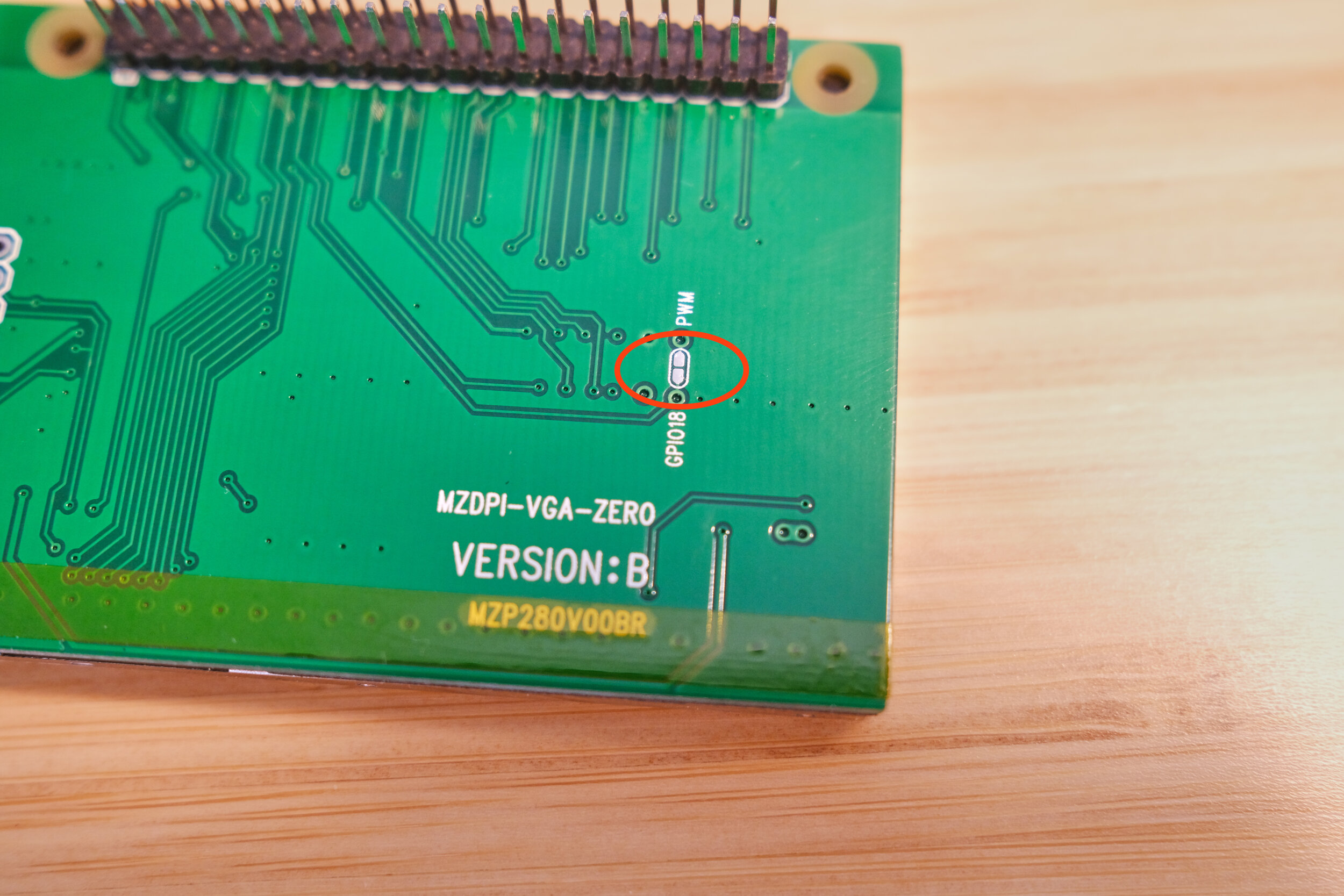
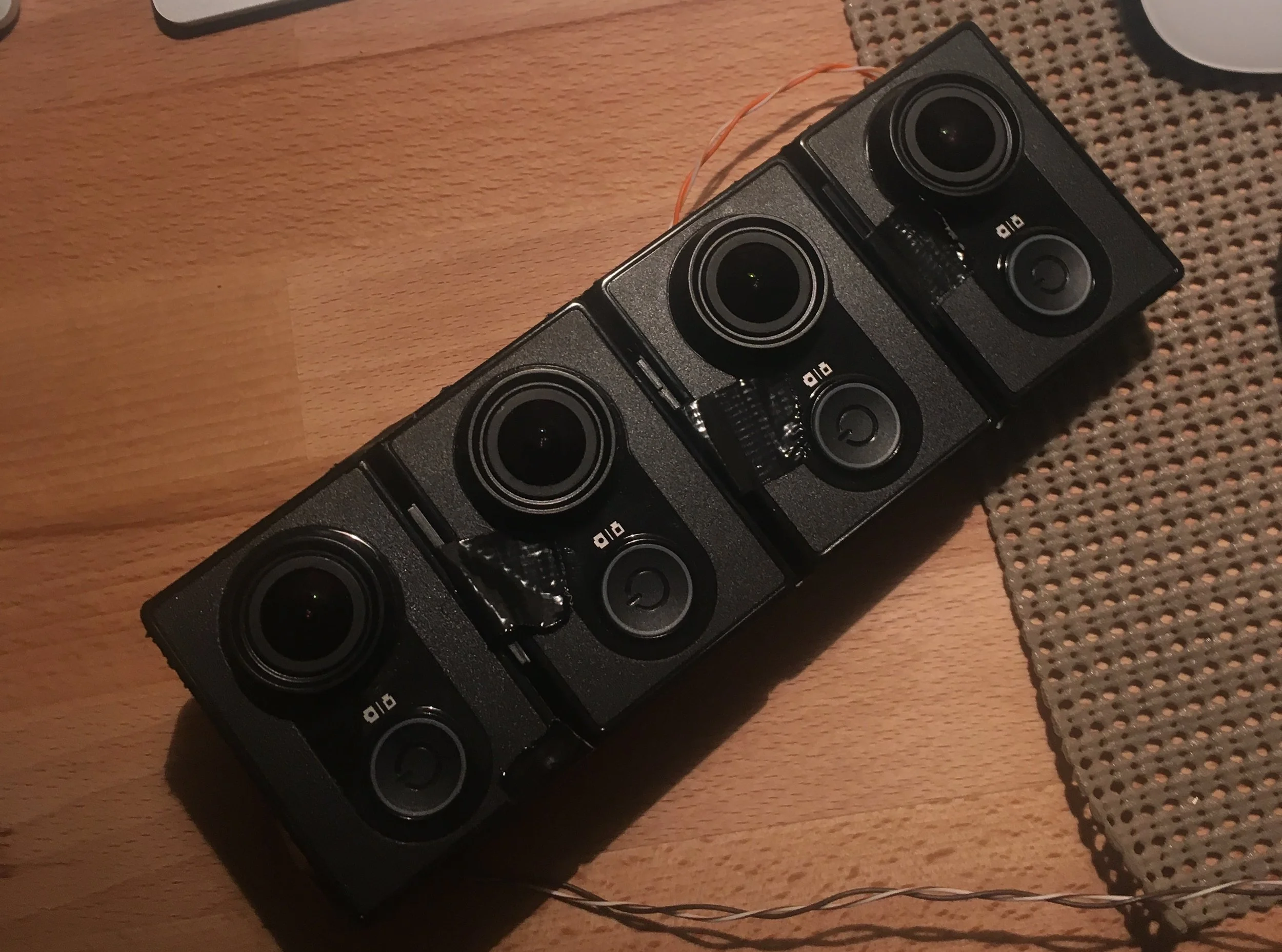
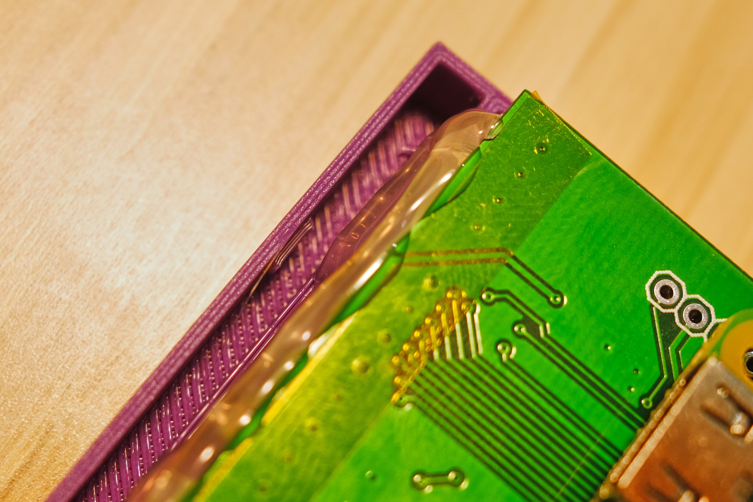
Lay the screen face down on your work surface with the pins facing North. You will see the jumper off to the right. We are going to solder this jumper, connecting the two pads. Place the iron against the pads to heat them up. After a second apply the solder. Remember always apply the solder to the pads, not the iron. The finished solder should look like this:

The next bit is the hardest bit of soldering. If you are newer to soldering maybe skip ahead to the Power and Audio Circuit for practice and come back here afterward. Don’ worry, you will be a soldering star in no-time.

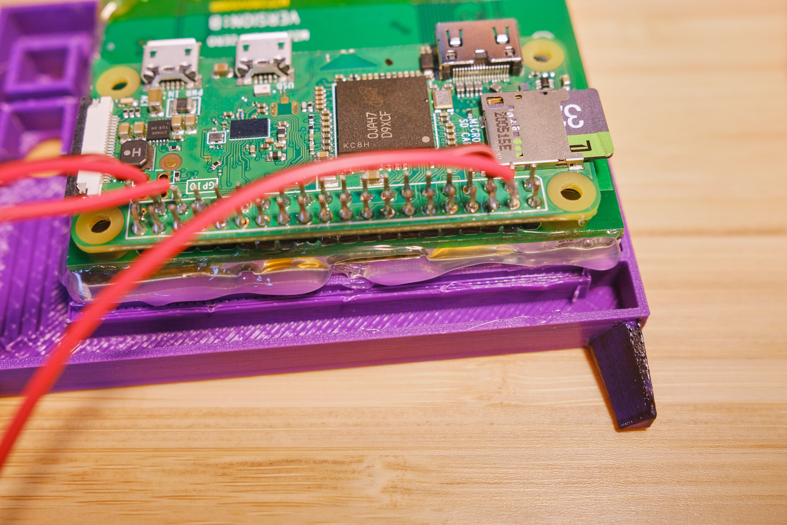
Place the Raspberry Pi zero onto the 40-pin connector on the back of the LCD screen. It’s important to keep the Raspberry Pi facing outward! I like to start by holding the corner of the Pi firmly in place and then quickly soldering the two leftmost pins. I’m a south paw like Stupid Sexy Flanders, so you might want to start with the two rightmost pins. Go slow and remember to heat the tiny pad and the pin with the iron, and apply the solder to the contacts, NOT THE IRON. Take breaks every few pins, you don’t want to overheat the Pi board.

Ok. Phew! Wipe the sweat off your forehead and get the shepherd's pie out of your knickers. You’re a solder champion now. Before we setup the rest of the hardware components, lets boot up the Pi and make sure everything works.

Installing the OS, LCD Drivers and Audio

Now lets prep the SD card. There are other options for this, but the Raspberry Pi Imager is the easiest in my opinion. Insert the SD card into your computer and open the Raspberry Pi Imager. We are going to use a different OS than the default. Click ‘Operating System’ and select ‘Raspberry Pi OS (Other)’. Then select ‘Raspberry Pi OS Lite (32-Bit)’. Next select the ‘Storage’ button. Pick your SD card from the list.
IMPORTANT: Make sure you select the SD card. If you accidentally select, say, an external hard drive that is plugged into your computer, the next step will erase that hard drive. Always be sure to double check. Finally select ‘Write’. It may ask for your desktop password; this is just verifying that you want to erase and write this SD card.
After the image is written to the SD card remount (Eject and re-insert) it to your computer. We need to make a couple quick changes before we can put it in the Pi. I know, I’m shaking with excitement too.
We need to setup the Pi for headless boot. This way we can control / configure it from the comfort of our desktop. Ahhh, comfort. There are several guides out there for this bit, but in the name of being a complete guide here’s a quick rundown.
Open a text editor, I prefer Sublime. Create a new file and paste this bit in there:
country=US
ctrl_interface=DIR=/var/run/wpa_supplicant GROUP=netdev
update_config=1

network={
    ssid="NETWORK NAME"
    psk="NETWORK PASSWORD"
}
This file will allow your Pi to connect to your wifi network when it boots. Replace NETWORK NAME and NETWORK PASSWORD with your wifi name and password. Be sure spelling, capitalization and spaces are correct. If you are not in the US be sure to set the proper country code as well. Now save the file as “wpa_supplicant.conf” onto the root of the SD card. It should be mounted as “boot”.
Create a new blank file and save it as “ssh” with no extension onto the SD card. Thats right, a blank file! This just enables the SSH protocol on the raspberry pi when it boots, which allows us to connect and control it.
Next let’s install the display driver. Download the driver zip from here. Unzip it and copy all of the files except mzdpi.dtbo onto the root of the SD card. Click yes when it asks if you want to override. Then copy the mzdpi.dtbo into the “overlays” folder.
Finally open “config.txt” on the root of the SD card. First find the line that says:
display_rotate=3And change it to:
display_rotate=1Next add the following line to the bottom of the file. This turns the screen on during boot.
gpio=18=op,dhSave and close the file. Eject the SD card from your computer.
Now you can insert the SD card into your Pi and power it up. You can use any usb charger that supplies 2.4 amp and a micro usb cable. The screen should come on and a bunch of text will fly past. Eventually you should see “My IP address is ###.###.###.###” where # is a series of numbers. Write those numbers down, you may need them. Once you see that you should be able to login from your computer.
Software Setup
Now if everything worked correctly you should be ready to connect to your pi from your computer. Launch terminal and type:
ssh pi@raspberrypi.localIf it takes a long time or doesn’t connect, try ssh pi@###.###.###.### with the number you wrote down earlier.

The default password is raspberry. Speaking of default password, we should take this moment to change the default password. If you don't, the King of England could just log in and start bossing your Pi around. You don’t want that do ya? DO YA? Thats what I thought. Run the Raspberry Pi OS setup by typing:
sudo raspi-configChange your password, save and exit. No need to reboot yet, that will happen soon enough.
Next we need to update. Run the following command:
sudo apt-get updateOnce it completes run:
sudo apt-get upgrade
These two commands might take a few minutes. During the install process it will ask you if you want to install press Y. Press Y unless you can find the ‘Any’ key.
Now lets install usbmount. This will allow us to easily mount our USB drive when the time comes. Run:
sudo apt-get install usbmountAnswer Y when prompted. Once it finishes we need need to edit a file to enable auto mounting on the pi. If this is your first time typing the word ‘nano’ I should tell you that nano is a terminal text editor that lets you edit and save files. Imagine you are launching a full screen text editor. The up and down keys will browse through the file. The left and right arrow keys will place a cursor on a line. To exit you hit CTRL+X. It will then ask you if you want to save. You can type Y and then ENTER for yes and then ENTER again to save. If you’ve never used a terminal text editor before it can be a little disorienting at first. Just think of all the skills you are learning!
Lets edit our first file:
sudo nano /lib/systemd/system/systemd-udevd.serviceScroll down to where it says PrivateMounts=yes and change it to:
PrivateMounts=noNow lets do a quick reboot before continuing.
sudo reboot -h nowPhew! Ok, we are making our way through. Take a break and marvel at how far you’ve come. Once it has rebooted connect again over ssh.
Enabling Audio
Now we need to configure a few things for the boot process. We need to enable the audio output and reconfigure some GPIO pins. By default the Pi Zero does not have any audio output, aside from HDMI. We can however enable PWM (Pulse Width Modulation) audio and reroute the audio over to a GPIO pin (All of those tiny pins you soldered to the screen). The TFT screen is using, well just about all, of the GPIO pins. There are a few that are unused though. We have to do a few clever routings to get audio output.
Lets edit the boot configuration file:
sudo nano /boot/config.txt Add the following to the bottom. This enables audio, and routes the audio to GPIO Pin 18, and 19.
dtparam=audio=on
dtoverlay=audremap,enable_jack,pins_18_19
Save and exit (CTRL+X, Y Enter, Enter)
Now pin 19 is free, but the screen uses pin 18 for the backlight. We need to re-configure pin 18 during boot, or else the screen will never come on.
sudo nano /etc/rc.localAdd the following lines towards the bottom of the file, right before exit 0:
raspi-gpio set 18 op dl
raspi-gpio set 19 op a5
raspi-gpio set 8 a2
raspi-gpio set 7 a2
Next we need to change some boot commands to hide all of that ugly boot text, and to disable any kind of screen blanking.
sudo nano /boot/cmdline.txtEverything in this file is on one really long line of commands. Start scrolling right through the line.
See where it says console=tty1? We need to change that to:
console=tty3Continue scrolling to the end of the line. Along the way remove where it says:
fsck.repair=yesNow at the very end of the line add:
consoleblank=0 logo.nologo quiet splashThe whole line should look similar to this. Don’t copy and paste this though, as some thing will be different on your pi.
console=serial0,115200 console=serial0 root=PARTUUID=a0ba64cd-02 rootfstype=ext4 elevator=deadline rootwait consoleblank=0 logo.nologo quiet splashSave and exit (ctrl X).
Now we need to install omxplayer: a lightweight video player.
sudo apt-get install omxplayerNow we need to install the scripts that will play videos, and make use of the power button and knob that we will install. First, lets install git. Git is a tool that allows downloading code from a repository.
sudo apt-get install gitNow lets install the scripts that will play videos on loop and also read the input from the front buttons. Run these two lines:
cd ~/
git clone https://github.com/buba447/simpsonstv
Moving the videos onto your Pi
It’s time to transfer the videos over! First, lets change directories:
cd ~/simpsonstv/videosThis is the directory that the video player will look for videos to play.
Lets plug in our USB drive to the spare usb port on the pi, you will need a micro USB adapter for this. Once the USB Drive is connected lets copy all of the videos from it to our Pi. The videos should be on the thumb drive in a folder named ‘encoded’. Run the following command to copy the videos onto your Pi:
sudo cp -R /media/usb/encoded/. ~/simpsonstv/videosThis will probably take some time. Take a break, have a glass of water, go ponder at the clouds.

Ok now final step! We want our video player and button control scripts to run every time the pi boots. We will create a service for both scripts and set the Pi to run them whenever it boots. First let’s setup the button service:
sudo touch /etc/systemd/system/tvbutton.service
sudo nano /etc/systemd/system/tvbutton.service
Now paste the following into the editor:
[Unit]
Description=tvbutton
After=network.target

[Service]
WorkingDirectory=/home/pi/simpsonstv/
ExecStart=/usr/bin/python /home/pi/simpsonstv/buttons.py
Restart=always

[Install]
WantedBy=multi-user.target
Now let’s setup the player service:
sudo touch /etc/systemd/system/tvplayer.service
sudo nano /etc/systemd/system/tvplayer.service
Paste the following into the editor and save:
[Unit]
Description=tvplayer
After=network.target

[Service]
WorkingDirectory=/home/pi/simpsonstv/
ExecStart=/usr/bin/python /home/pi/simpsonstv/player.py
Restart=always

[Install]
WantedBy=multi-user.target
Now lets set these two services to start on boot:
sudo systemctl enable tvbutton.service
sudo systemctl enable tvplayer.service
Now, lets shut down the pi. After it shuts down, unplug it from the power source.
sudo shutdown -h now
Phew, all this hacking has made me thirsty. Lets order a tab. Take a break, and then let’s finish up the hardware side.
Soldering the Power and Audio Circuit
Grab your trusty soldering iron and the rest of your components; we’ve got a little bit of soldering left to do. It might be helpful to set this all up on the breadboard first, but if you are feeling embiggened by the noble spirit, go ahead and solder it up. I cut nearly all of the wires to 4-5 inch lengths. This will make the final assembly a bit easier.
The Audio Circuit

Lets start with the audio circuit. These are the things you will need:
3 wire pairs
1k Potentiometer
2.5 w mono amplifier
4 ohm speak
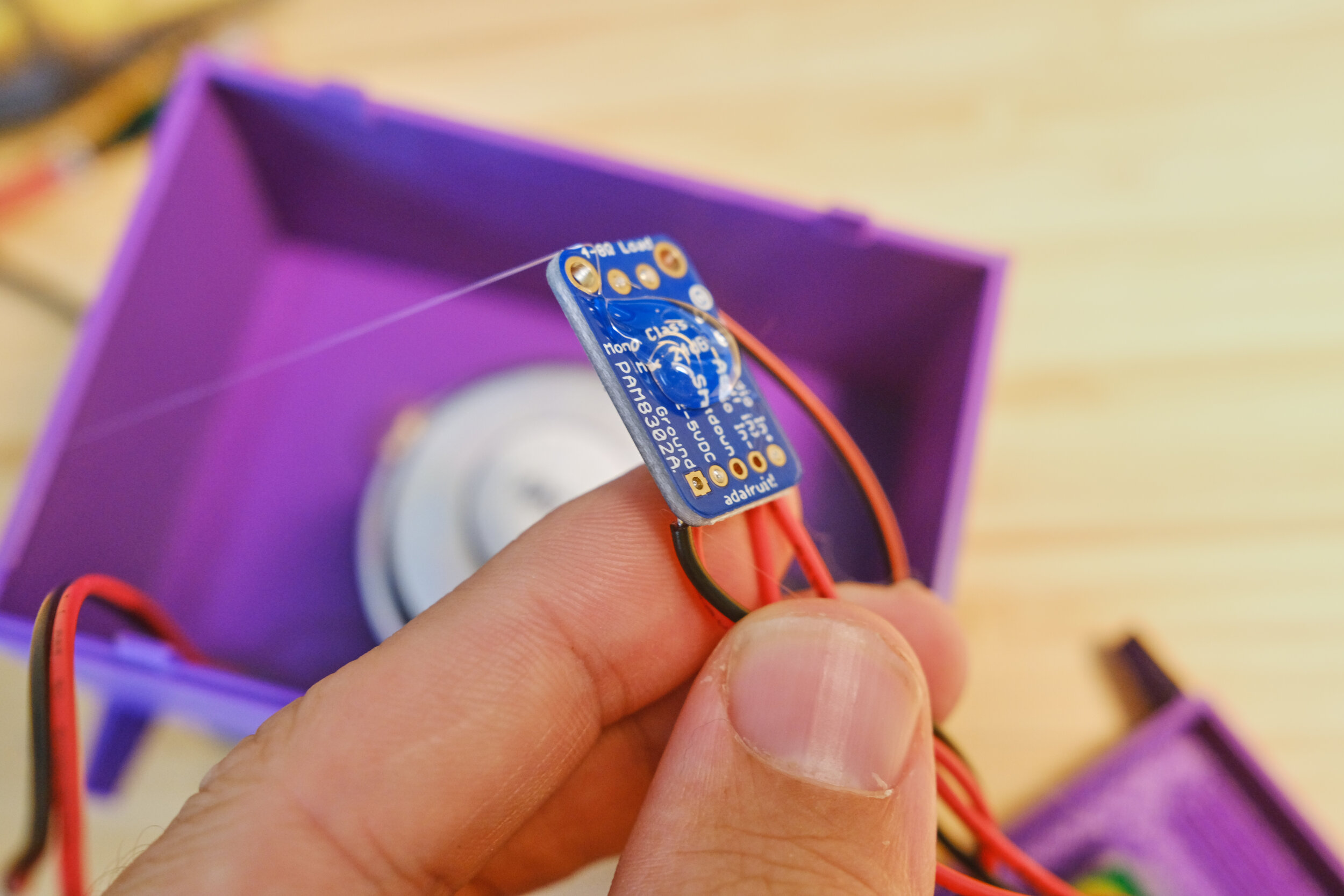
To start, let’s solder up the outgoing wires on the amplifier.

Take one black/red pair and solder the black to the ground and the red to the pad next to the ground. These are the wires that supply the amplifier with power. Mark them if you’d like, or take a mental snapshot. Next, solder a single wire to the Audio In+; it should be the outermost pad. This is the wire that supplies the audio signal to the amp (we will connect these to the Pi later). The amp should look something like the above image.

Now we need to solder a small jumper cable between the A- and the GND of the amp as shown above.

Now lets solder up the speaker and potentiometer. A potentiometer, or POT, is a variable resistor with three legs. As the knob is turned, the resistance applied to the output is increased or decreased, which results in a lower or higher current. Essentially, it makes the signal weaker. This will control the volume going into the speaker. We need to solder a wire to the input (the center pin) and one to the output (the rightmost pin).

Now for the speaker. Solder a wire to one of the two speaker leads (doesn’t matter which one). Next solder one of the wires coming from the POT to the other speaker lead. It should look like the above image.
Finally let’s connect the speaker circuit to the amplifier. There are two output pads on the opposite side of the amp from the input. Solder the loose speaker wire to one and the loose wire from the POT to the other. The final audio circuit should look like this:
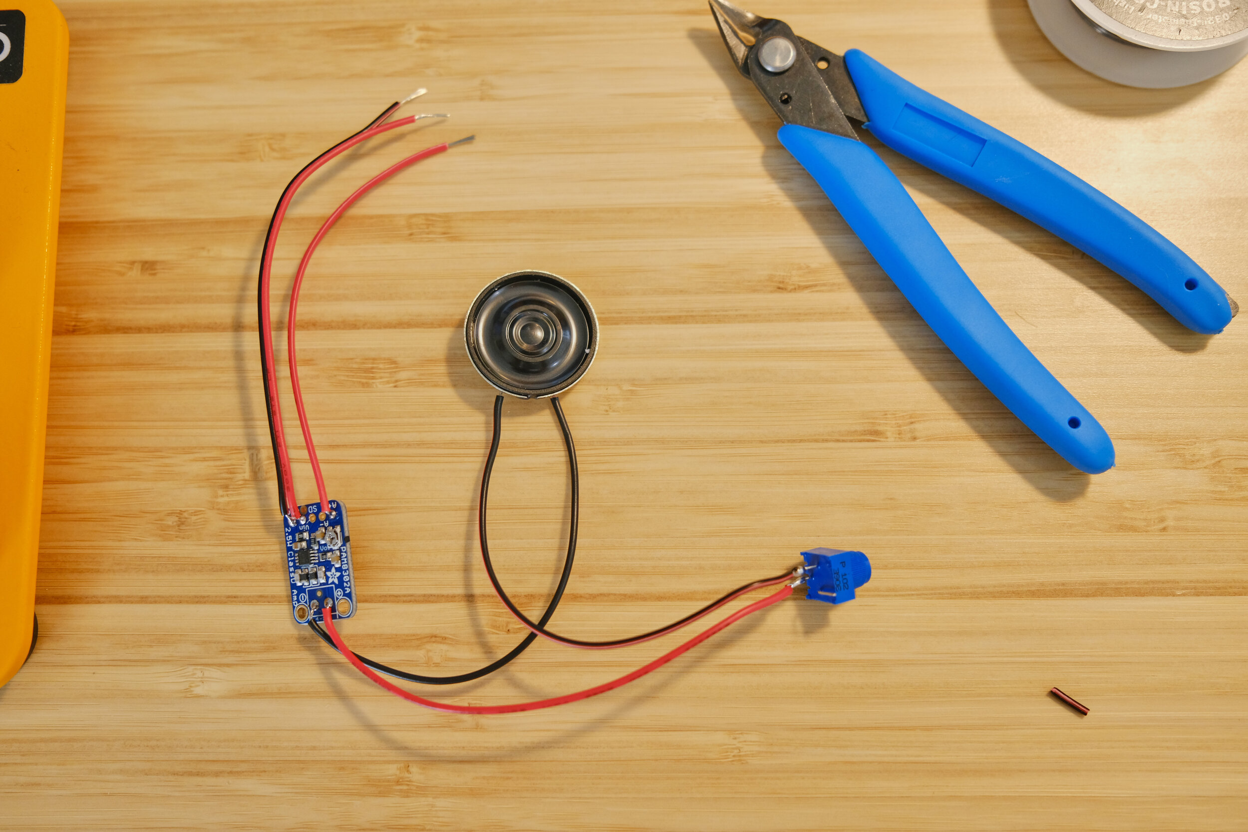
Before we continue, let’s make sure that the amplifier is turned all the way up. Look on the board and you will see a small silver knob with a Phillips screwdriver marking. Use a small screw driver to turn the knob up.

Your speaker circuit is ready!
The Power Button and Power Cable
The power button is super easy to hook up. Solder a wire to the center pin, and another wire to the outermost right pin. It should look something like this:

The power cable is essentially a USB adapter cable. We need our Micro USB breakout board, a Micro USB header, and a short length of wire.

Solder a red wire to the positive, and a black wire to the ground of the breakout board as pictured.

Now, solder the other end of the two wires—being careful to match the colors—to the USB header. The extension cable should look like this:

Putting it all together

Ok, let’s connect the power button to the Pi First. Above is a pinout of the Raspberry Pi from pinout.xyz. It is oriented with the sd card facing North. We are going to connect the two wires of the power button to GPIO 26 and the ground that is below it. Like so:

Now, let’s wire up the audio circuit. Take the two power wires that you marked earlier and connect the red to the 5v+ and the black to the Ground in the upper right hand, next to GPIO 14, like so:

Take the remaining wire and connect it to GPIO 19, which is next to the power button.
Ok. Super scary, but all of the soldering should be done! Holster that bad boy, but do unplug it and wait for it to cool down first.
Let’s make sure everything works. Plug in your Simpsons TV and wait for it to boot. The screen should stay off unless the screen power button is engaged. Eventually some videos should start playing! Test that the power button toggles on and off and that the audio knob raises and lowers the volume. To tweak the sound, turn the volume all the way up and adjust the small POT on the amp until the audio is no longer distorted. Phew! All the scary stuff is over. Time for the final stretch!
Mounting the components
Now let’s put the housing together. We’re almost there! Plug in your trusty hot glue gun. While we wait for it to heat up let’s take care of a few small things.

If you want to go the extra mile (why would you come this far to not go a little further?), you can take some dark purple acrylic paint and paint a few details onto the case. Paint the legs and the inlay around the front of the screen. It should be pretty quick work; the case was designed for easy painting. If you mess up, use a wet paper towel to wipe off the paint. You will probably want to do two coats.

Mounting the Controls

Take the power knob, the one with the square on the back, and push it down onto the power button. There should be a bit of resistance and a satisfying snap.

Next take the volume knob and apply a bit of super glue to the back. Press the front of the POT into the knob. Hold it. Hold it. Hold it. Phew there we go.
Now, lets mount the components onto the front of the TV. Be sure to remove the anti-scratch sticker from the front of the screen. Mmmmmhmmm, pleasing. Also remove the power extension cable from the Pi. Place the screen face down onto the front housing. Make sure that the screen is oriented properly, with the Pi on the south side.
Using the hot glue gun, first dab the top left corner of the screen. Cover it with glue from the top edge down to the housing. Next run a bead of hot glue along the top and bottom edges of the screen. Be careful to not entirely fill the void in the case at the top or bottom where the casing snaps go.
The Controls
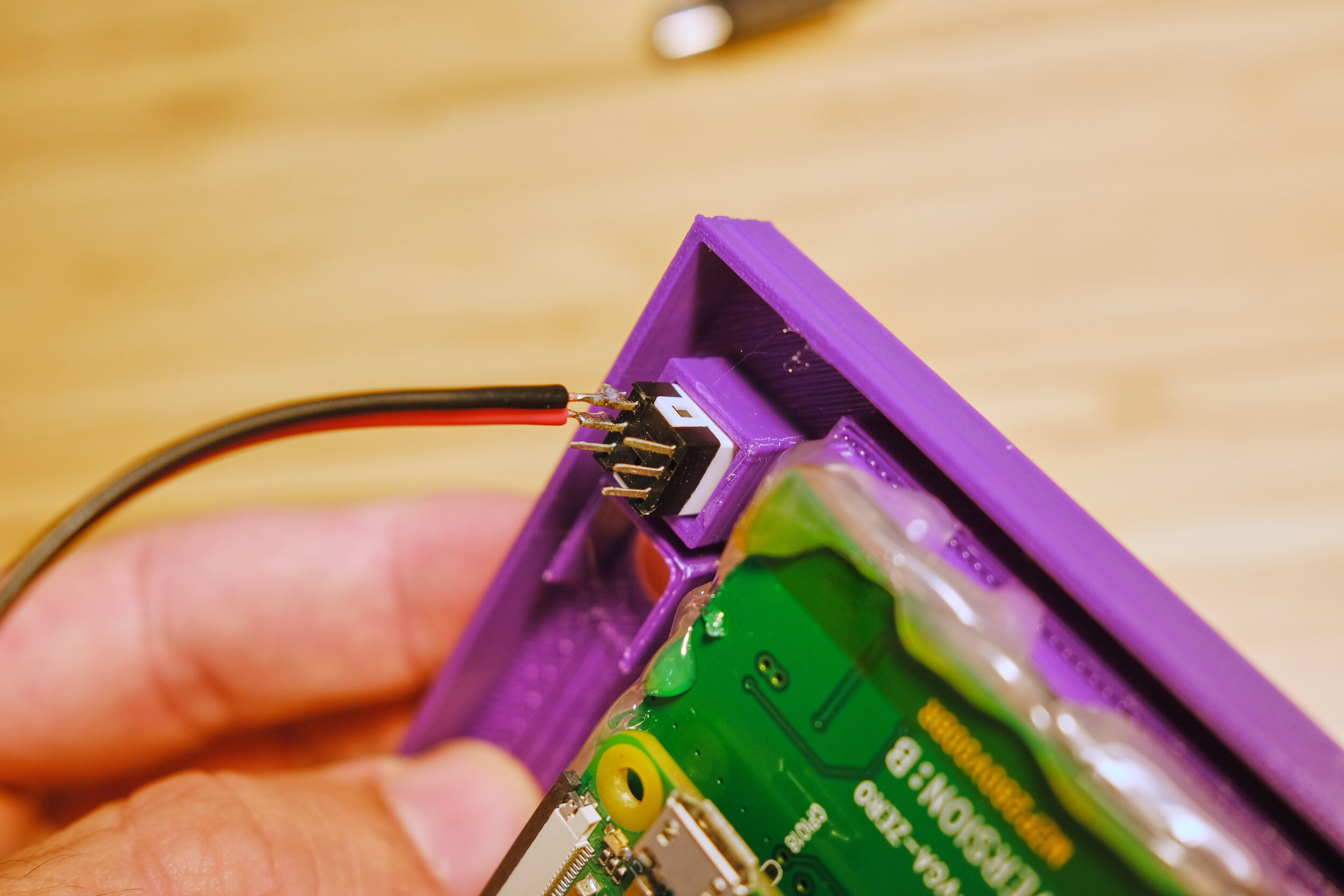
Now place the power button in the top knob housing. First make sure that the button is disengaged. Press the button and release until it is at it’s tallest position. Gently press it into the housing until the knob comes out the front of the housing. Be careful to not press the button itself in, or it will never be able to disengage. Use some hot glue to secure the button housing in place. Hold in place until the hot glue dries.
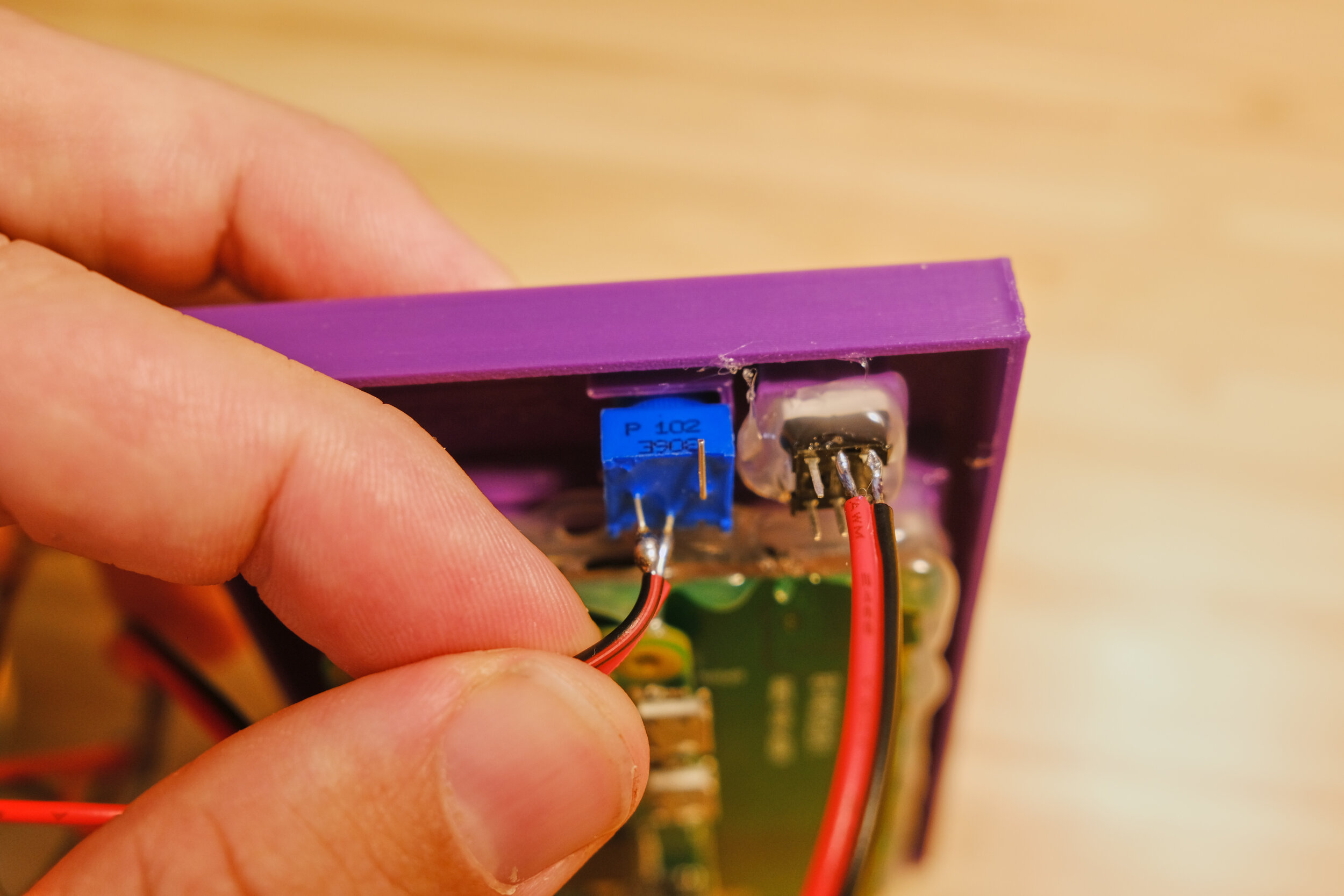
Follow the same procedure for the volume knob. Don’t press it in too firmly, or the knob won’t turn.
TV Housing
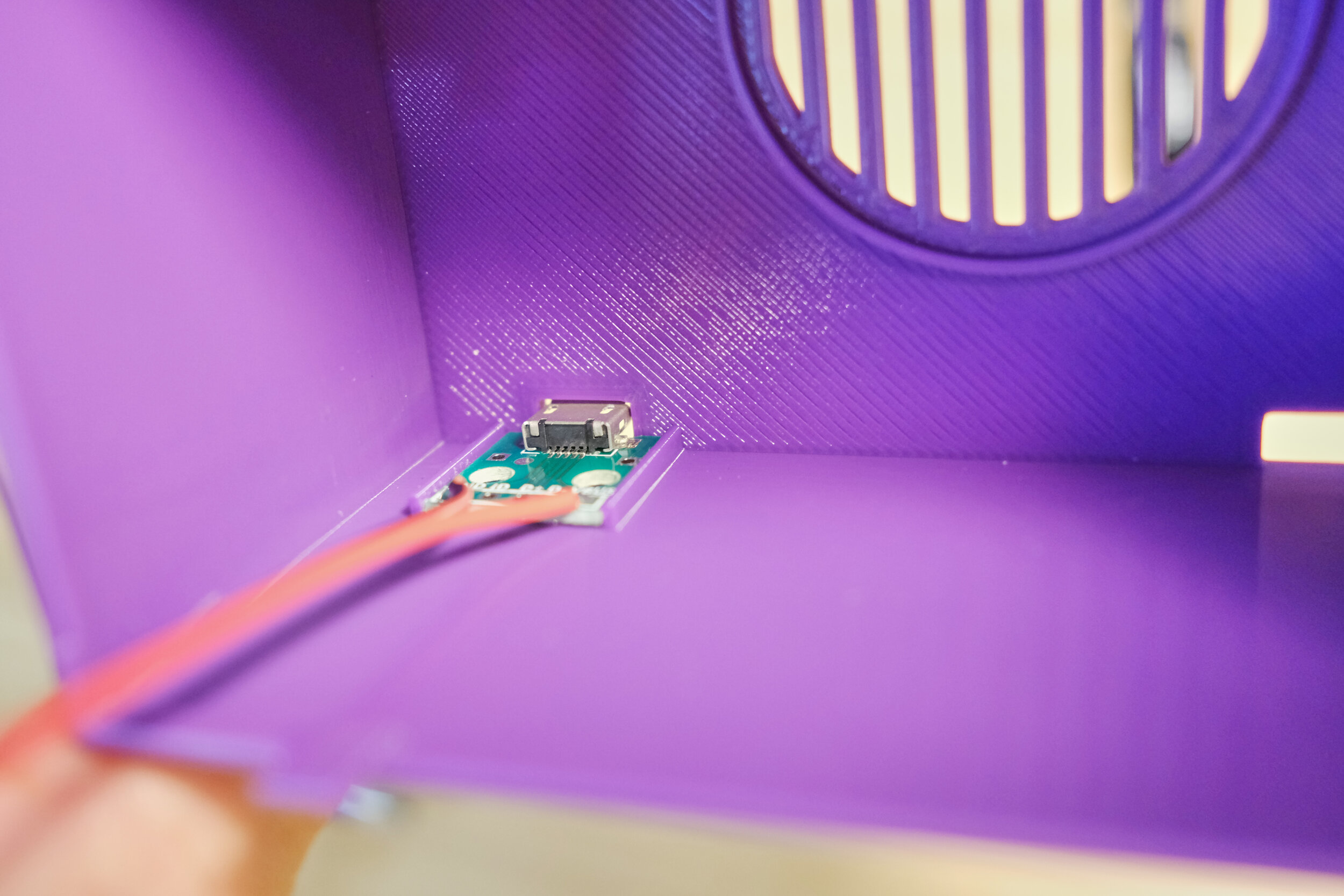
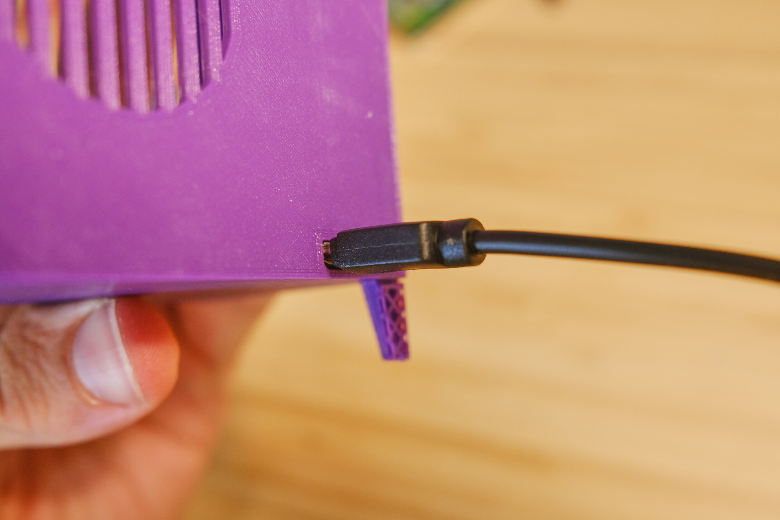
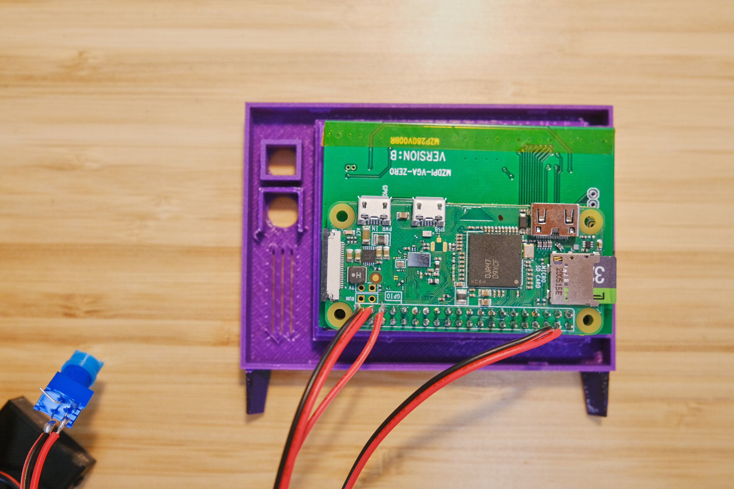
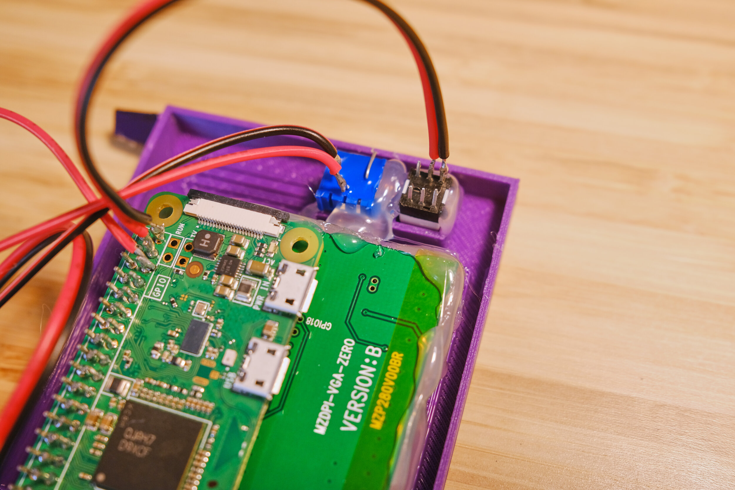
Ok, home stretch! Let’s mount the remaining components into the large TV housing. Grab your usb power extension cable. Place the component board on it’s seat in the bottom left corner of the housing. I find this next step is easier if you plug a micro usb cable into it after placing it (leave everything unplugged from any power source). The cable helps to hold it into place.
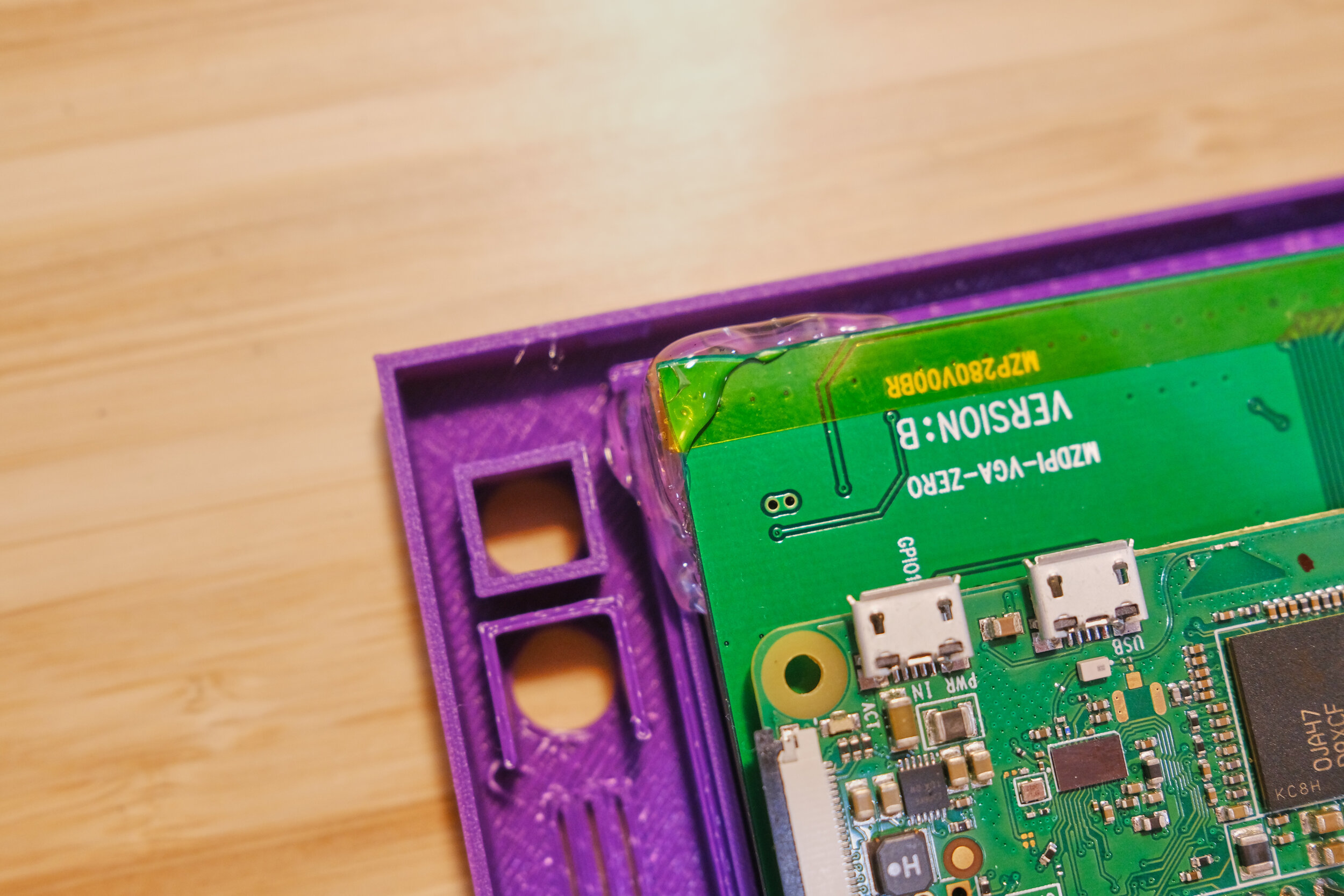
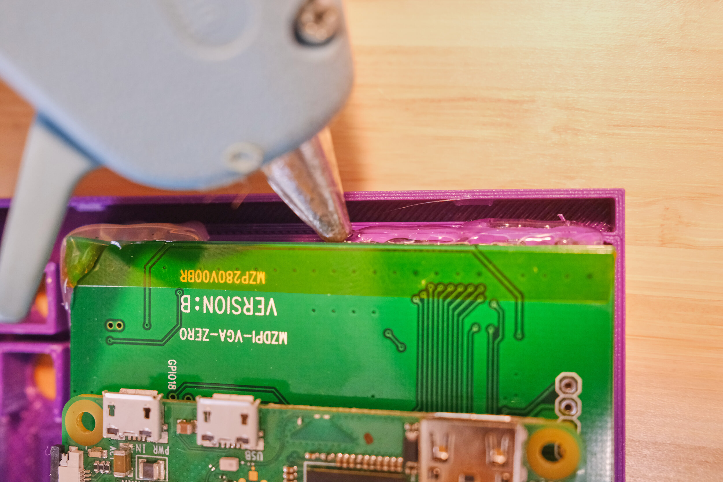
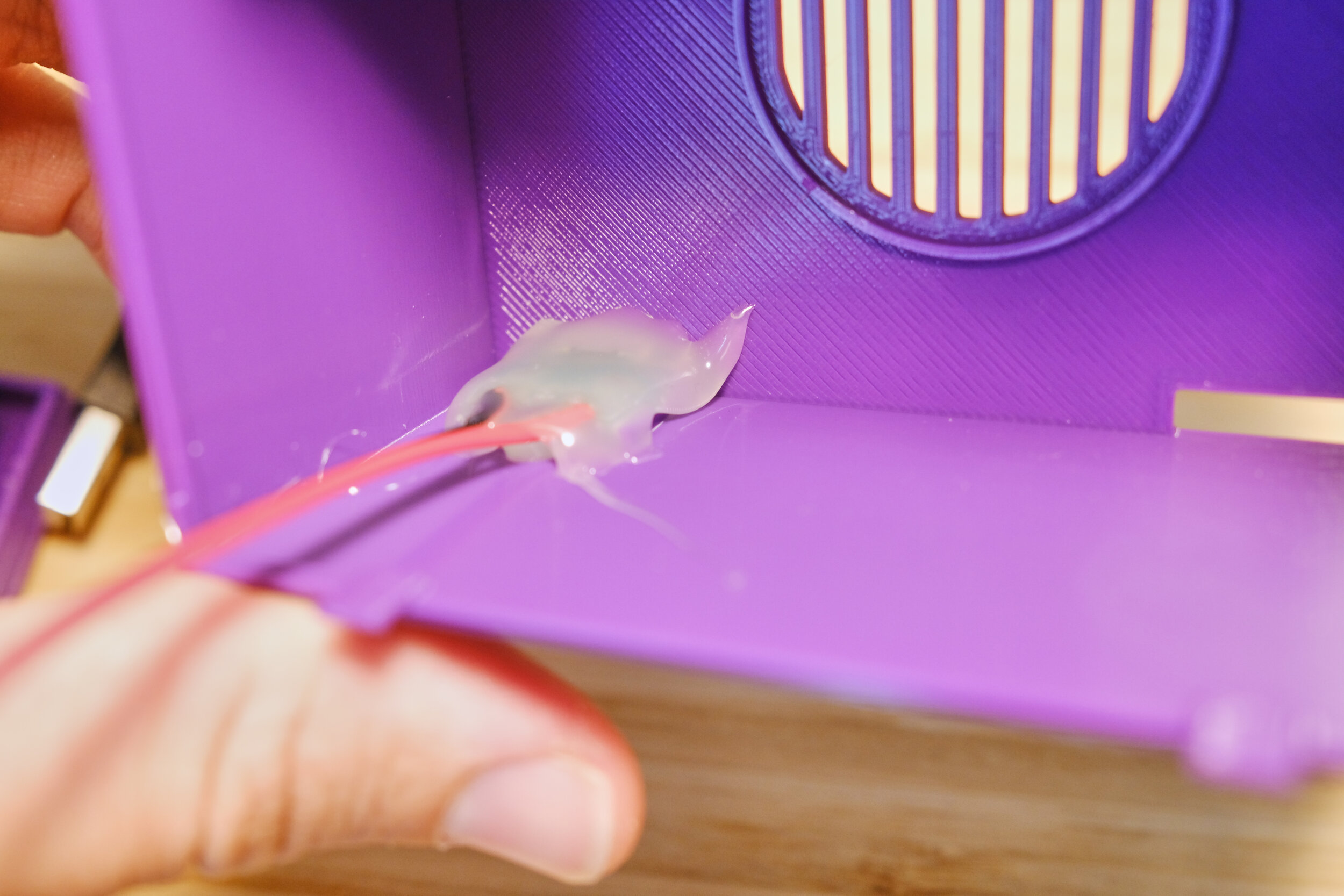
Use a bit of hot glue to hold it into place. Then, generously cover the whole thing, covering the edges and connecting it to the housing. Wait for the glue to cool and turn white before moving on.

Now the speaker! Place the speaker face down on the back ring. Use hot glue to secure it around the edges. You don’t need to glue the whole thing, just a couple of points. Again, wait for the glue to dry and check that it’s secure before continuing.
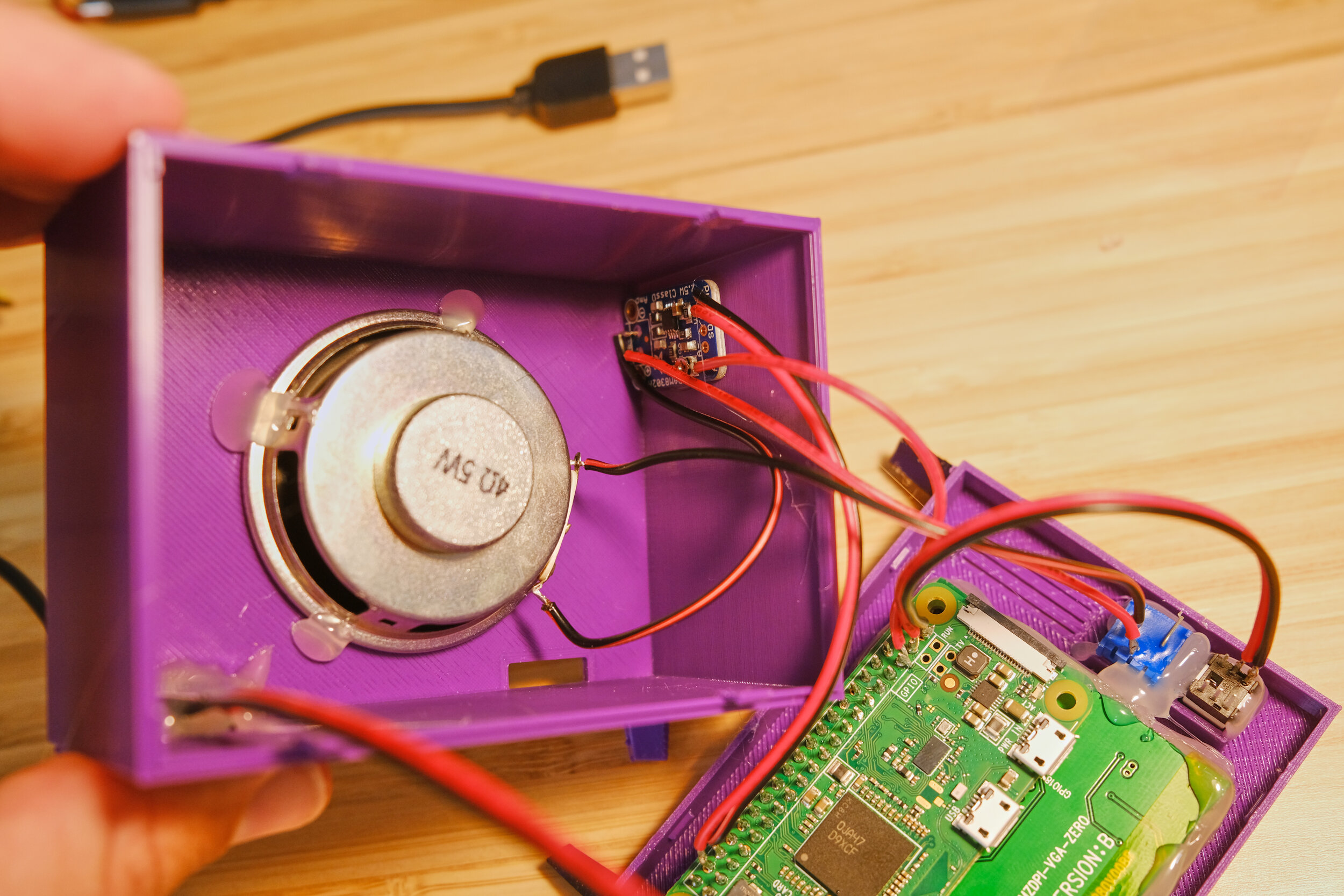
Finally the amplifier. For this one just put a dab of glue on the underside and press it into the side wall of the enclosure. Easy peasy. Ok! Great work. You are done with the hot glue gun, so holster it next to your soldering iron. Check everything and make sure it’s secure. remove any hot glue spider webs that you find.

One more thing before we close it up. It’s time to connect the power extension cable into the Pi’s usb power port.
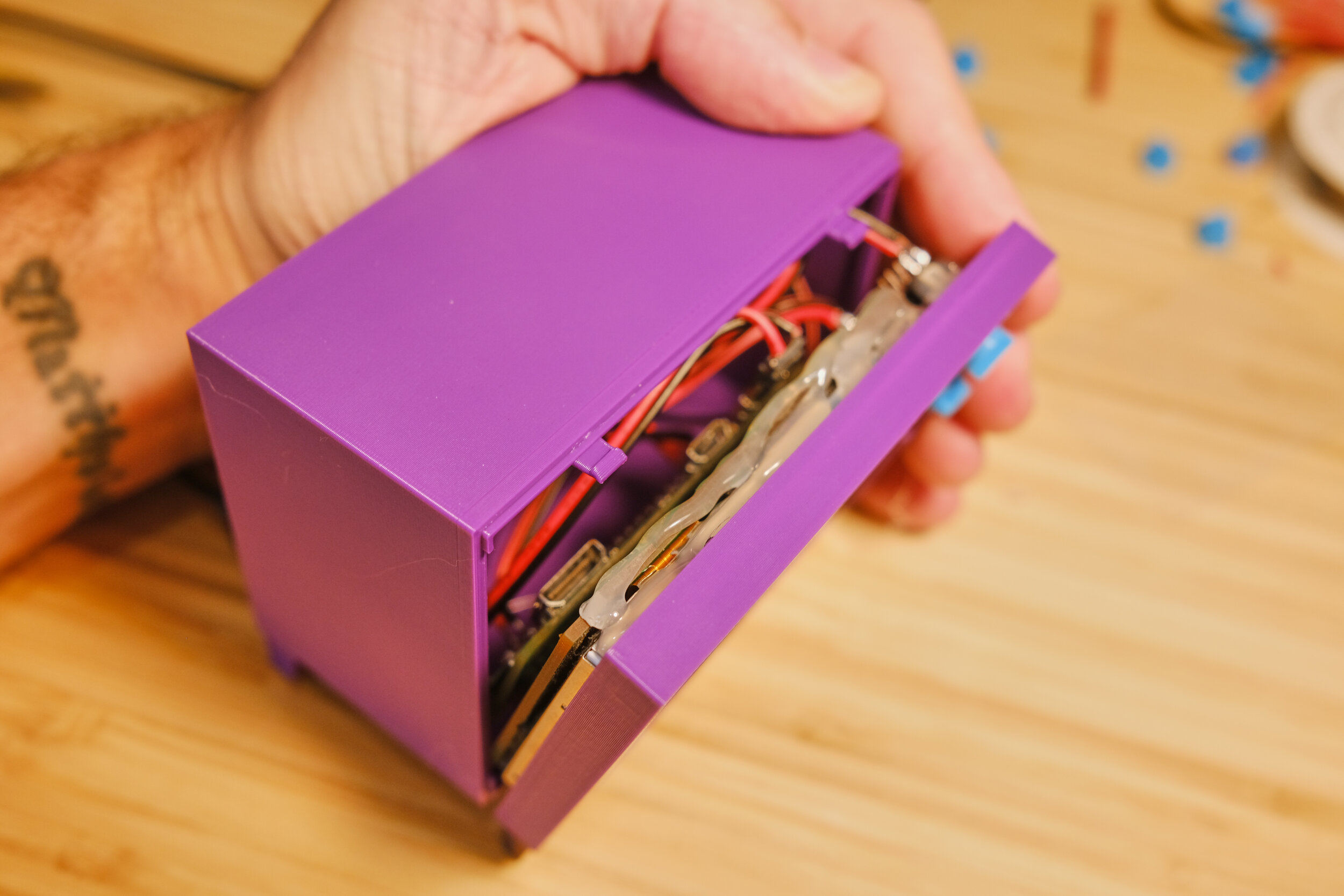
Time to close it up! The front of the TV snaps onto the rest of the tv using four case snaps. Start by aligning the front onto the back. Carefully fold any wires into the enclosure. Starting at the bottom press and snap the front onto the case. Nice!
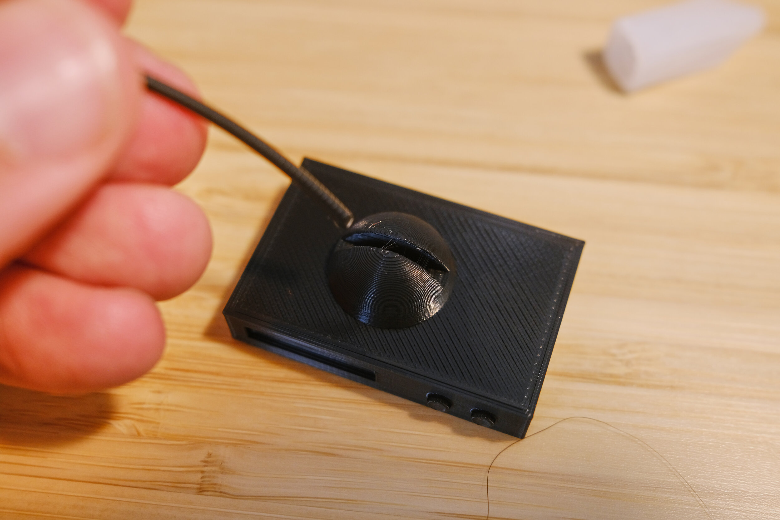
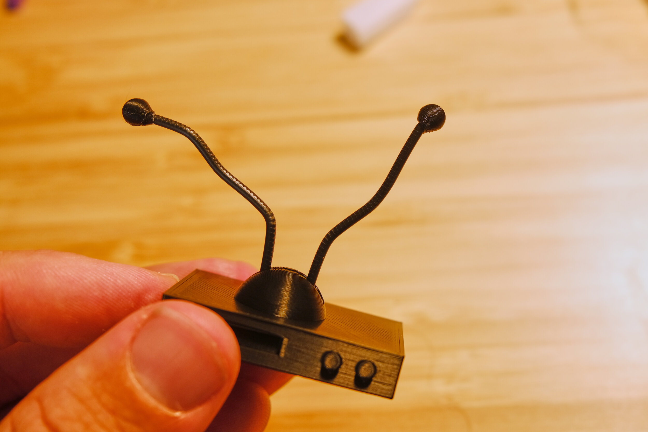
Time to assemble the VCR. Cut two short lengths of black printer filament for the antenna. Using a bit of super glue, press them into the two antenna holes on top of the VCR. Now do the same with the two antenna toppers.
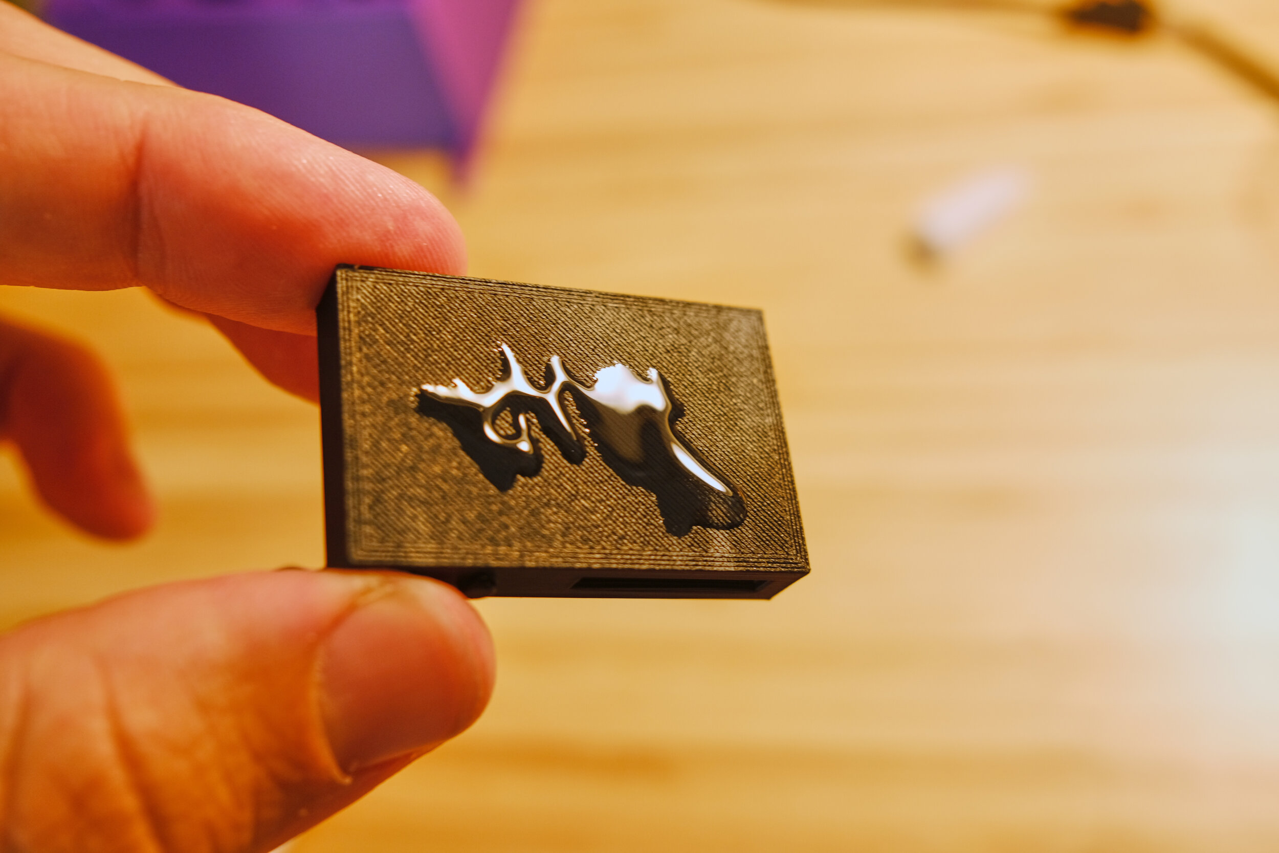
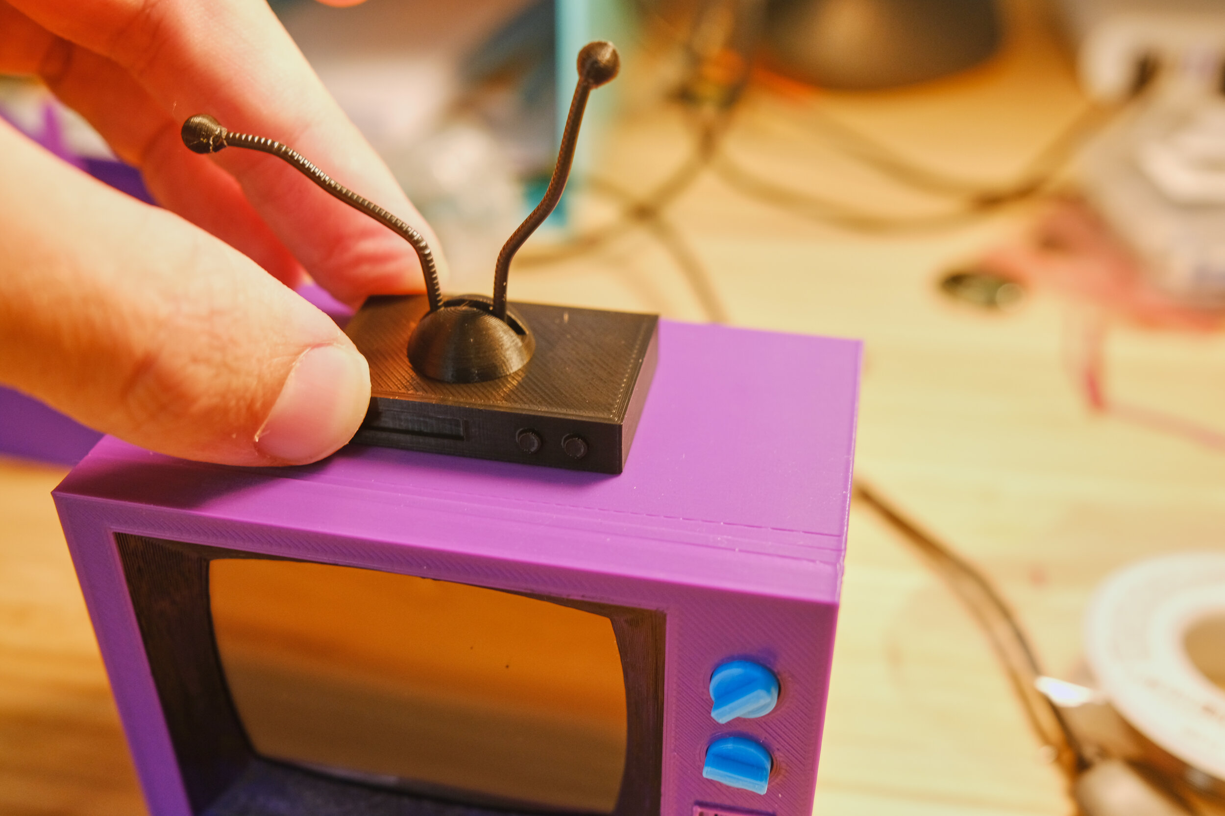
Put a bit of super glue on the bottom and place the VCR on top of the TV. Don’t worry about being too precise; do you think Homer had his VCR perfectly centered?

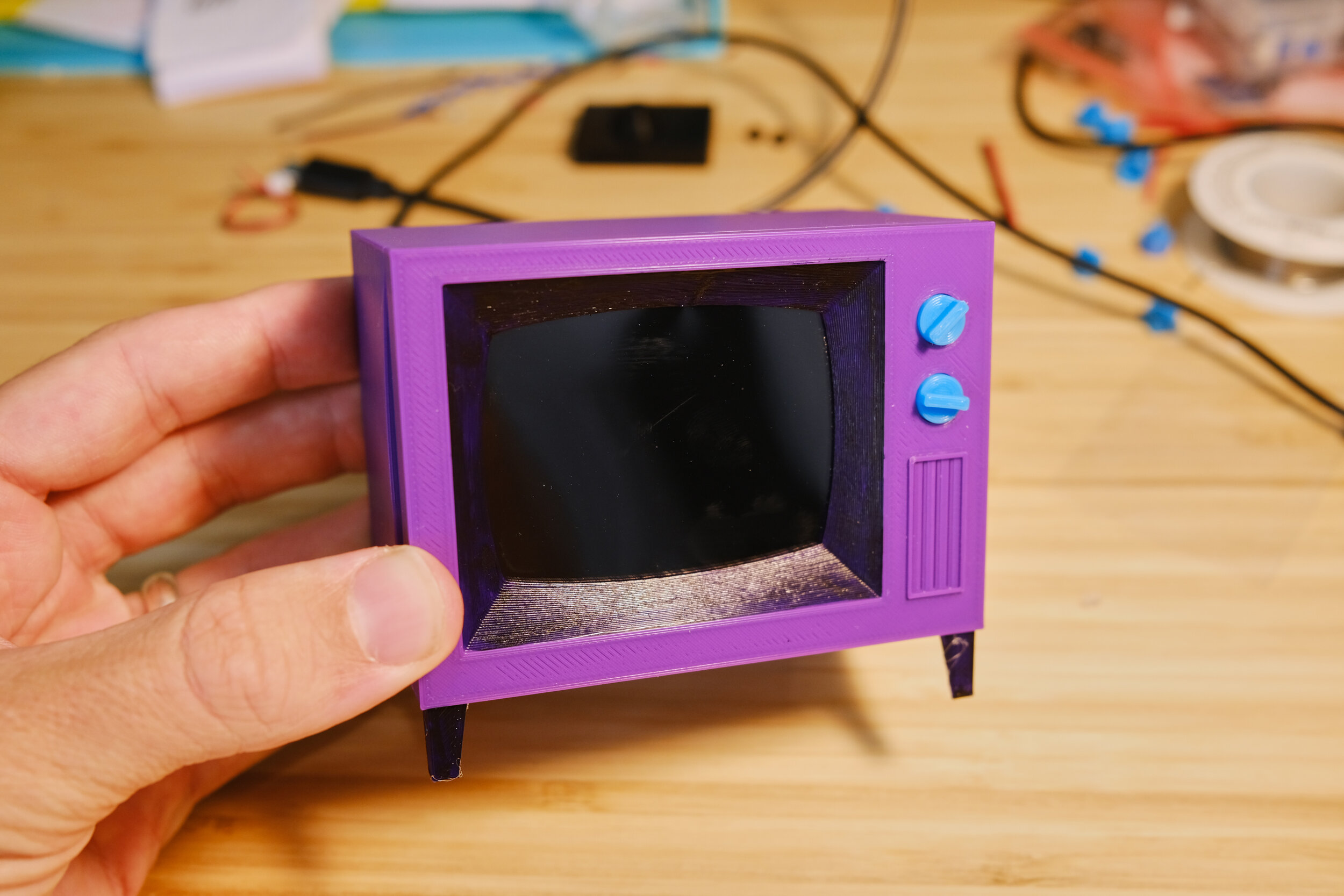
Et viola! You have a tiny TV.
Congrats on making it this far—you are awesome! Tweet me a pic of your finished TV; I’d love to see it. If you liked this guide and want to thank me, you can donate a few dollars here.
Upgrades
But wait! There’s more. Upgrades. Here are a few ideas for upgrading your Simpsons TV.
Faster Boot Time
Yeah, I hate waiting for my Simpsons TV to boot too. The first version was built on PipaOS—a super light weight version of Jessie that booted almost instantly. It was fabulous. Unfortunately, as I was writing this guide, Jessie was discontinued and is no longer supported. There is a newer version of PipaOS built on Stretch, but I haven’t tried it yet. You should be able to follow this guide with PipaOS, but I haven’t tested it. You might run into some errors.
Gapless Playback / TV On-Off Graphics
This is a fun one! I’ve managed to get near gapless playback working with omxplayer by running two instances of omxplayer and controlling them using DBUS. This is a little advanced and takes some finessing. The other catch is that you need to know the runtime of each video, which can be found with fprobe. This adds another layer of complexity to the whole thing.
I was able to add TV graphics such as interstitials, on off blinks, and even a little logo in the bottom corner using Kivy. Kivy is a lightweight graphics package for python. It must be compiled for your os of choice, which is a more advanced topic. I find that something like Kivy is the best for the the Pi Zero, since it is not powerful enough to play video and also render out html. If you decide to go down this rabbit hole there’s a lot of interesting quirks to get omxplayer and Kivy to play together. I’d be happy to write a guide sometime if there’s enough interest.